Showing posts with label sensor. Show all posts

Wednesday, December 18, 2013

Heat Sensor Circuit Diagram

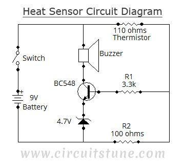
This simple heat sensor circuit could senses heat from various electronics device like computer, amplifier etc. and generate warning alarm. It could senses heat from environment also, but here I mention “electronics device” because it is being using mostly in electronic device to protect them from overheat.

Circuit diagram of heat sensor:

Heat sensor circuit
Fig-1: Schematic Circuit Diagram Of Heat/Temperature Sensor


Thermistor, 110 Ohms:

Thermistor (110 Ohms)
Fig-2: 110 Ohms Thermistor
As it is a heat sensor circuit, here a thermistor is used as a heat sensor. It is a thermal measurement device and has a variety of usages including temperature sensor/ heat sensor. The thermistor used in this circuit is a NTC (Negative Temperature Coefficient) type thermistor. When temperature increases, its resistance goes decrease. Therefore, NTC thermistor’s resistances are inverse of temperature.

Circuit Description:

You have seen, in this simple circuit diagram of heat sensor, a few number of components is used including a BC548 transistor, a 110 ohms thermistor etc.
  • BC548: BC548 is a TO-92 type NPN transistor, as its alternative you can use 2N2222, BC238, BC548, BC168, BC183 etc. they all have almost same characteristic.
  • 110 Ohms Thermistor: A 110 Ohms thermistor is used to detecting heat. I have told already about it.
  • Buzzer: A buzzer is used with +9V and collector of transistor. When the temperature/ heat exceeds a certain level then it make an alarm.
  • 4.7V Zener diode:  It is used to limit the emitter current of BC548.
  • 9V Battery: A 9V battery is used as a single power source.
  • R1, R2: A 3.3K 1/4w resistor is used as R1 and 100 ohms 1/4w as R2.
  • Switch: Here in this circuit the switch used is a simple SPST switch. You can either use the switch or not, choice is yours. It is not mandatory.
More...

Friday, April 12, 2013

Cheapest Ever Motion Sensor

The RS-455-3671 sensor used in the Automatic Rear Bicycle Light challenge printed in  the July/August 2010 model will additionally be replaced by way of a motion sensor that prices nothing instead of a fiver or thereabouts. 

 
The replacement is a do-it-yourself device, constructed from elements simply found within the workshop of any digitals fanatic. Effectively it works as a variable resistor, depending on the acceleration force to which the software is  submitted. A prototype introduced a resistance of 200 kΩ when now not shifting, and a hundred ninety kΩ when shedding about 1 cm.

Constructing is easy. Cut off a bit of about 10 mm of copper tubing. Take a bit of conductive foam, the kind used to supply safety to integrated circuits. Cut a rectangular piece of 10  x 50 mm. Roll up firmly except it may additionally be push-fitted securely into the copper cylinder. Then insert a conductive wire in the direction of the centre of the cylinder, bend it and (optionally) add protective plastic sleeving to each and every side. This is the first contact. Finally, solder a skinny wire to the copper cylinder. This is the second contact. The foam resistance is stress based. 

Consequently, when the tool transfers due to an external power, the inertia of the cylinder lead tos varying pressure within the foam, leading to a small change of resistance between the interior conductor and  the cylinder. Because of that, it’s necessary to verify the cylinder vibration shouldn't be limited in any way through the connecting wire or the PCB. 

The comparator circuit proven right here is able to resolving the resistance change of the proposed foam/wire/copper sensor, permitting it to become mindful of the motion of a automobile for alarm or different functions. 


Author : Antoni Gendrau – Copyright : Elektor
More...